Milling process commonly used equipment (2)
(B) The main types of milling machine fixture
In the milling process, the fixture is often mounted on the milling machine table, and the workpiece together with the fixture for the feed movement with the table. According to the feed method of the workpiece, the milling machine fixture can generally be divided into the following two types:
1. Straight feed milling fixture

This kind of fixture performs linear feed movement with the milling table during the milling process. Figure 8-26 shows the double-station linear feed milling fixture. The jigs 1, 2 are mounted on the duplex turret 3. When the jig 1 is in operation, the workpiece can be attached to and detached from the jig 2. After the workpiece on the jig 1 is processed, the table 5 can be withdrawn, and then the station is turned 180° so that the workpiece on the jig 2 can be processed and the workpiece can be loaded on the jig 1 at the same time.


2. Circular Feed Milling Clamp
This type of fixture is often used on milling machines with rotary tables. The workpieces, together with the fixtures, make continuous, slow-rotary feed motions with the table and can be loaded and unloaded without stopping. Figure 8-27 shows a circumferential feed mill fixture. The workpiece 1 is successively clamped on a jig installed along the circumferential position of the rotary workpiece table 3, the milling cutter 2 is continuously milled, and the rotary table 3 performs a continuous rotary motion to sequentially feed the workpieces into the cutting. This example is machined with a milling cutter head. According to the processing requirements, it is also possible to use both milling heads for simultaneous roughing and finishing.
(III) Structural Analysis of Special Milling Clamps
1. Lever milling bevel milling fixture
Figure 8-28 shows the process of milling two inclined surfaces on a lever type part. The shape of the workpiece is irregular. Figure 8-29 shows the single-piece milling fixture for machining this part in batch production.
The workpiece is positioned on the shoulder positioning pin 9 with the finished hole 22H7 and the end face, which limits the five degrees of freedom of the workpiece; the circular surface is positioned on the adjustable support 6 to limit the rotational freedom of the workpiece. In order to achieve the complete positioning of the workpiece.
Clamping the workpiece to the platen 10 main hook, which structure is shown in a sectional view AA and the other near the working surface of the floating auxiliary clamping mechanism, when the tightening nut mechanism, the pawl 2 and 3 move towards each other, while Clamp the workpiece. When the opening end of the pawl 3 has three axial grooves, forming three valve springs continue to tighten the nut, the cone sleeve 5 that is forced expansion valve opening spring, it locks in a fixture, thereby enhancing the rigidity of the clamp, so as milling Generate vibration.

The specific bottom surface A is placed on the workbench of the milling machine. The two positioning keys 8 of the fixture are installed in the T-slot of the worktable so that the milling fixture and the milling machine maintain the correct position. Therefore, the bottom surface A of the milling fixture and the work surface B of the positioning key are the joining surfaces of the milling fixture and the milling machine. The accuracy of the A-side and B-side surfaces of the positioning element work surface and the milling fixture is a factor that affects the installation error A. The axis line of the positioning pin 9 of the clamp should be perpendicular to the shoulder surface of the locating pin 9 on the B surface of the positioning key. The plane of the shoulder should be perpendicular to the bottom surface A, and their accuracy affects the installation error of the clamp.
The clamp element is a knife cutter block 7 to determine machining position, i.e. the position of the knife block is reflected position of the tool, and therefore the positioning accuracy of the cutter block element is the effect adjustment error? T of factors. The distance between the axis line of the knife block 7 and the positioning pin 9 in the jig is 18±0.1 mm and 3±0.1 mm, which are factors influencing the adjustment error.
The accuracy of positioning elements, ie, 22H7/g6, 36±0.1mm, is a factor that affects positioning error ?D.
Figure 8-30 shows the process diagram for milling the keyway and oil groove of the lathe tailstock sleeve. The outer circle and both ends of the workpiece have been machined.
This process uses two milling cutters for simultaneous processing. Figure 8-32 shows the fixtures for mass production. At the station I, the keyway is milled with a three-faced disc cutter. The outer circle and the end face of the workpiece are positioned on the V-blocks 8, 10 and the thrust pin 12, which limits the five degrees of freedom of the workpiece. At station II, the oil groove is milled with a circular-arc milling cutter. The outer circle of the workpiece, the machined keyway and the end face serve as a reference for positioning, and the V-blocks 9, 11, the positioning pin 12, and the thrust pin 14 are completely positioned. Because the lengths of the key grooves and the oil grooves are not equal, in order to be able to complete processing at the same time, the positions of the two thrust pins may be offset from each other and designed to be adjustable for adjustment.
The clamp is hydraulically driven and linked to clamp. When the pressure oil enters the upper cavity of the hydraulic cylinder 5 from the oil circuit system, the piston is pushed downward, and the hinged pressure plate 7 is driven to clamp the workpiece by supporting the nail 4, the floating lever 2, and the screw 3. In order to make the press plate evenly clamp the workpiece, each link of the interlocking clamping mechanism adopts a floating connection. To be as small as possible to ensure that the clamping is stable and reliable.
The technical requirements of the fixture affect positioning errors, adjustment errors, installation errors, please readers analyze.

(4) Design points of milling machine fixture
1. The overall design of the milling fixture and the clamp
In the milling process, the cutting force is relatively large, and the work of the cutting teeth is discontinuous cutting, which may cause shock and vibration. Therefore, the clamping force requires a large amount to ensure the reliable clamping of the workpiece, so the milling machine fixture must have sufficient strength. And stiffness, if necessary, stiffeners should be set.

In order to improve the stability of the milling machine fixture installed on the machine and the vibration resistance under dynamic conditions, the structure of various devices should be compact, the processing surface should be as close as possible to the work surface to reduce the center of gravity of the fixture, and the ratio of height H to width B of the general fixture Should be limited to the range of H/B ≤ 1~1.25.
Milling productivity is high (cutting time is short). When designing the fixture, consider how to quickly install the workpiece to shorten the auxiliary time. Generally, the fixture is also provided with components for determining the position and direction of the tool, so as to quickly adjust the fixture, the machine tool and The relative position of the tool.
In addition, a large amount of chips are generated during the milling process, and there should be enough space for chip removal. For heavy-duty milling machine fixtures, for the convenience of handling, rings should be installed on the clamps.
2. Installation of milling fixture
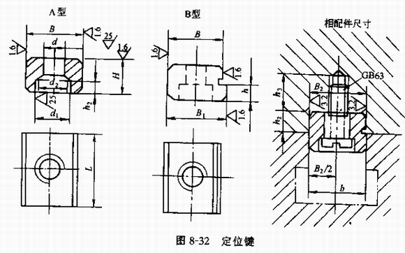
The installation position of the milling machine fixture on the milling machine table directly affects the positional accuracy of the machined surface. Therefore, the installation method must be considered when designing. In general, we install two keys positioned beneath the base in a fixture, the two positioning key fitted into a T-slot milling the same table, and then the T-bolts and washers, nuts fastening clamp work On the stage.
The commonly used positioning keys are rectangular, as shown in Figure 8-32. The positioning key can withstand the torque during milling, its structure size has been standardized, and the design should be selected according to the T-slot size of the milling table. For type A keys, the fitting dimensions with the clamp groove and the table T-slot are both B, and the tolerance band can be h6 or h8. The slot width B2 of the positioning key installed on the fixture is the same as the B dimension, and the tolerance zone can be h7 or js6. In order to improve the accuracy of the use of B-key, with the T-slot size B1 with 0.5mm grinding amount, and the actual size of the machine T-slot configuration.
In addition, there are two ear seats that need to provide T-shaped bolts on the clip, as shown in Fig. 8-33. The structural dimensions have also been standardized. Refer to the relevant fixture design manual.
To ensure the installation accuracy, the distance between the two positioning keys is as large as possible. When installing the jig, let the key abut on the side of the T-shaped groove to reduce the effect of the gap.
For the fixture with high precision, the positioning key is often not provided, and a narrow long surface is machined on the specific side of the clip as the alignment base surface when the fixture is installed.
If the clamp width is large, two ear seats can be provided on the same side, but the distance between the two ear seats must be the same as the spacing between the two T-shaped grooves on the table. If the positioning accuracy is required to be high, the size b of the lower part of the positioning key can be repaired, or the jig can be pushed to the side of the T-shaped groove when installing the jig. To avoid the impact of the gap.

3. Tool setting device for milling machine fixture
After the milling machine fixture is installed on the workbench, the relative position of the milling cutter to the fixture is also adjusted so that the distance processing can be performed. In order to align the tool relative to the workpiece surface to be machined quickly and correctly, a tool setting device can be used on the fixture. The tool setting device is composed of a counter block and a feeler gauge, and its structure size has been standardized. The structure of various knife blocks can be selected according to the specific processing requirements of the workpiece.

Figure 8-34a shows a schematic diagram of the tool setting, where 1 is the counter block, 2 is the feeler gauge and 3 is the milling cutter.
The purpose of using a feeler gauge is to avoid direct contact between the tool and the counter block, so as not to damage the blade or cause premature wear of the block. When using, place the feeler gauge between the cutter and the cutter block, judging by the sensation of twitches, suitable to moderate.
The commonly used feeler gauges have two kinds of flat feeler and cylindrical feeler gauges, which have been standardized. As shown in Fig. 8-35b and c, they are the structures of commonly used standard feeler gauges. Generally, the size of the feeler gauge should be indicated on the general fixture drawing. The thickness H of the flat feeler (Fig. b) is usually 1, 3, and 5mm, and the basic dimension d of the round feeler (Fig. c) is ?3mm or ?5mm. The design can be referred to GB2244 in the "Fixture Parts and Components". -80 and GB2245-80.
The structure of the standard block can be found in GB2240-80, etc. of the National Standard "Fixture Parts and Components". If the standard tool block is inconvenient, non-standard special tool block can be designed. The knife block is usually made as a separate element and is positioned on the clamp with screws and positioning pins. The position of the knife block is to facilitate the use of feeler gauges and to prevent loading and unloading of the workpiece. The position size (H, L) of the tool block working surface is generally taken from the positioning surface, and its value shall be equal to the average value of the corresponding dimension of the workpiece and then subtracted or added with the thickness S of the feeler gauge. The tolerance is usually 1/3~1/5 of the corresponding dimension tolerance of the workpiece.
In order to simplify the jig structure, sometimes the tool setting device is not used in the production, but the trial cutting method, the standard piece countermeasure method or the dial indicator is used to correct the position of the positioning element relative to the tool.
Notch Wire Element is made by wrapping specially treated thin stainless steel notch wire around the cylindrical filter core. The element filters impurities through a gap between the stainless steel notch wires. It can be easily washed and reused.
Advantage of notch wire element,
1. Simple structure and robust form
2. Apertures can be controlled in terms of few microns.
Micron accuracy : 10,15,25, 30, 40, 50, 60, 70, 80, 100, 120, 150 , 180, 200, 250 and above
3. impurities adhered to the element can easily be eliminated by back washing or air blowing
4. Offers more than 10 times filtration area when compared to wedge wire cylinders & 25 times more area when compared to stainless steel mesh filter element
5. Can handle fluids having high viscosity, ideal for high temperature/pressure applications

Notch Wire Element
Automatic Backwash Filter,Auto Backwash Filter,Stainless Steel Notch Wire Element,Notch Wire Element
Xinxiang Tianrui Hydraulic Equipment CO.,LTD , https://www.filterelement.pl